
Solution:
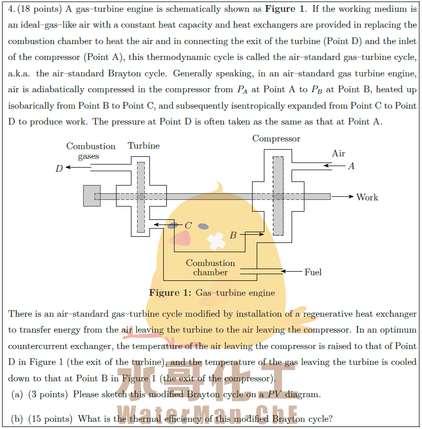
A gas–turbine engine is schematically shown as {\bf{Figure 1}}. If the working medium is an ideal–gas–like air with a constant heat capacity and heat exchangers are provided in replacing the combustion chamber to heat the air and in connecting the exit of the turbine (Point D) and the inlet of the compressor (Point A), this thermodynamic cycle is called the air–standard gas–turbine cycle, a.k.a. the air–standard Brayton cycle. Generally speaking, in an air–standard gas turbine engine, air is adiabatically compressed in the compressor from $P_A$ at Point A to $P_B$ at Point B, heated up isobarically from Point B to Point C, and subsequently isentropically expanded from Point C to Point D to produce work. The pressure at Point D is often taken as the same as that at Point A.
\vspace*{-0.5em}There is an air–standard gas–turbine cycle modified by installation of a regenerative heat exchanger to transfer energy from the air leaving the turbine to the air leaving the compressor. In an optimum countercurrent exchanger, the temperature of the air leaving the compressor is raised to that of Point D in Figure 1 (the exit of the turbine), and the temperature of the gas leaving the turbine is cooled down to that at Point B in Figure 1 (the exit of the compressor).
\begin{parts}
\part [3] Please sketch this modified Brayton cycle on a $PV$ diagram.
\part [15] What is the thermal efficiency of this modified Brayton cycle?
\end{parts}